
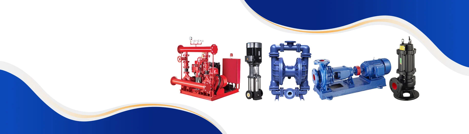
Working Conditions and Common Usage Misunderstandings of Single-Stage Centrifugal Pumps
Working Conditions and Common Usage Misunderstandings of Single-Stage Centrifugal Pumps
Working Conditions of Single-Stage Centrifugal Pumps
1. The suction pressure shall not exceed 1.0 Mpa, and the maximum working pressure of the pump system shall be no more than 1.6 Mpa (i.e., pump suction pressure + pump head ≤ 1.6 Mpa). The static pressure test pressure of the pump is 2.5 Mpa.
2. The ambient temperature is lower than 40℃, and the relative humidity is less than 95%.
3. The volume content of solid particles in the conveyed medium shall not exceed 0.1% per unit volume, and the particle size shall be smaller than 0.2 mm. Note: If the medium contains fine particles, please specify this when placing an order, so that wear-resistant mechanical seals can be equipped accordingly.
Common Misunderstandings in Single-Stage Centrifugal Pump Operation
It is essential to learn about common operational misunderstandings of single-stage centrifugal pumps to avoid equipment faults and ensure stable operation. The typical mistakes are summarized as follows:
1. Installing the horizontal section of the water inlet pipeline horizontally or upward
This installation method will cause uneven water flow distribution when water passes through the elbow and enters the impeller. If the diameter of the water inlet pipe is larger than the pump inlet, an eccentric reducer must be installed, with the flat side facing upward and the inclined side facing downward. Incorrect installation will lead to air accumulation, reduced water output, failure of water suction, and abnormal impact noise. If the inlet pipe diameter is equal to the pump inlet diameter, a straight pipe section must be installed between the pump inlet and the elbow, with a length of no less than 2 to 3 times the pipe diameter.
2. Excessive elbows on the water inlet pipeline
Too many elbows on the inlet pipe will cause air accumulation inside the pipeline, reduce the vacuum degree of the pipe and pump, lower the pump’s suction head, and decrease water delivery capacity. The correct installation requires the horizontal pipeline to tilt slightly toward the water source, rather than being horizontal or upward.
3. Direct connection between pump inlet and elbow / Unreasonable inlet position
If the distance between the pump inlet and the bottom or wall of the water tank is smaller than the pipe inlet diameter (or less than 1.5 times the diameter when there is sediment at the tank bottom), it will result in poor water intake, sediment and debris suction, and inlet blockage.
In addition, direct elbow connection will prevent the bottom valve from closing properly, causing water leakage. For inlet pipes equipped with bottom valves, the lower pipe section is recommended to be vertical. If vertical installation is restricted by terrain conditions, the angle between the pipe axis and the horizontal plane shall be above 60°.
If the water outlet is set above the normal water level of the discharge tank, it will increase the pump head while reducing the water flow rate. If the outlet has to be higher than the tank water level due to terrain limitations, install an elbow and short pipe at the outlet to form a siphon structure and lower the actual outlet height.
Moreover, excessive elbows on the inlet pipeline will increase local water flow resistance. All elbows shall be arranged for vertical turning instead of horizontal turning to prevent air accumulation.